|
|
|
ANOTHER DIY PHOTOGRAPHY GEAR PROJECT FOR THIS PROJECT I'M BUILDING A MOTORIZED 2 AXIS CAMERA GIMBAL FOR TIME-LAPSE VIDEOS. |
||||||||||||||
| CONTENTS:
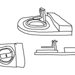
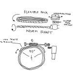
CONCEPT SKETCHES BEGINNING ASSEMBLY FINISHING ASSEMBLY PAINTING AND FINAL PHOTOS TESTING AND CONCLUSIONS | CONCEPT SKETCHES I went through several revisions trying to come up with a very pared-down and simplified design that only relied on a single motor in order to turn both axis. Initially I had planned on a linkage or gear mechanism that connected the horizontal axis to the pivot point on the vertical axis, resulting in the two being linked and turning in unison- the trouble with this design was that it really required parts being machined or even 3D printed, it wasn't something I could cobble together from off the shelf parts. In the end, I went with a much simpler to produce concept that relied only on gravity to actuate the vertical axis how I wanted. The idea with this final concept is that as the gimbal rotates, a long rod rides along a slope, gradually dropping down lower and lower, in turn tilting the camera and lens upwards as it rotates, giving a combined pan & tilt motion to the footage / images captured. The length and angle of the slope can be varied to achieve more subtle or dramatic translations in movement. Can't get much simpler that that I reckon, so that's the design I'm building. Click the images below to see the concept in all its glory, along with some rough calculations for speed and gearing requirements. | |||||||||||||
|
|
|
|
|
|
||||||||||
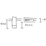
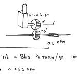
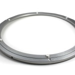
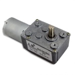
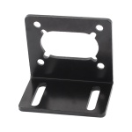
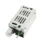
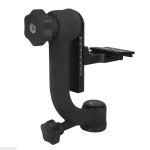
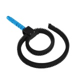
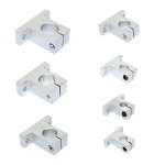
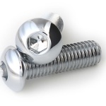
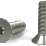
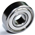
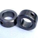
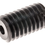
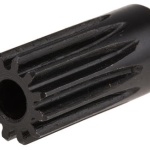
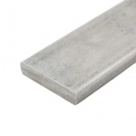
GATHERING PARTS With a good idea of what I wanted to build in my mind, I went off to the Bay of E to see what I could find in the way of parts. First item I needed was something I saw another person use in a video- James Burton of X-Robots with his BB8 version 3 droid, he used a 'lazy susan' turn table for the head mechanism in his project, and that was perfect for my needs also. Knowing I needed a way of rotating the turn table via gearing, I found a good source of flexible toothed rack- normally it's used for follow-focus on a camera lens, but the teeth just so happened to be mod 0.8 / 32DP, exactly what I needed. To drive the turn table I picked up a worm gear and couple pinions ( 13 and 25 tooth ), also in 32DP- both with a 6mm shaft. Needing some very low speeds I looked around and eventually found a motor and gearbox assembly that had an RPM of 0.6 running on 12v, perfect to get roughly 6-8 hours duration through the 90 degree arch I designed the gimbal to rotate through. A motor mount to match the gearbox was also sourced. As luck would have it I had some 6mm steel shaft lying around from dismantling old printers and scanner- a valuable source of useful bits and pieces of metal. At this point I picked up a cheap camera gimbal which would form the core of the project- ideally I'd have liked to use the old Manfrotto 393 gimbal, but it costs roughly 3-4 times as much- those little red logos add a lot to the price it seems. To mount the gearing and shafts I used some rather awesome little shaft holders- two with an 8mm hole for the 'follower' mechanism that rides down the ramp of the unit, and two with 16mm holes so that I could use bearings on the gear driven shaft. Speaking of which, I used a total of four 18x6x5mm metal shielded bearings, along with two 6mm shaft collars that lock in place via grub screws- these will prevent the main shaft from wandering out of place. I also picked up a cheap motor controller with a potentiometer for speed control and a switch for forward and reverse- I used a similar one on my motorized camera slider project. For mounting the hardware I used some countersunk hex head bolts and some button head bolts along with flanged nyloc nuts. To mount the gimbal to the turn table I picked up a 300mm x 40mm x 10mm long length of aluminium bar, and some 8mm OD aluminium tube which I sliced up to use as spacers between the turn table and the wooden base. For the base, I used some 18mm thick marine grade plywood- it didn't really need to be that thick, and MDF might have worked just as well, but I'd rather it was over built instead of too flexible and cause issues later on. From my boxes of bits I will use some assorted wire and switches to complete the wiring ( limit switches will be installed somewhere when the time comes ), battery-wise I plan to use the same one as I currently use on my camera slider- saves money since I can't use the gimbal and slider at the same time really, so one battery shared between them makes sense.
|
|
|
|
|
|
|
|
|
|
|
|
|
|
|
|
|
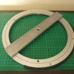
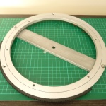
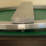
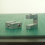
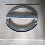
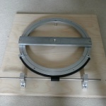
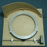
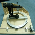
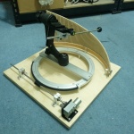
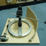
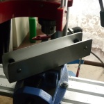
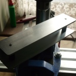
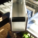
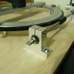
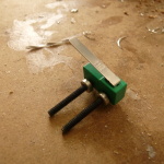
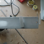
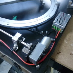
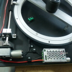
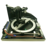
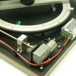
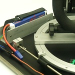
BEGINNING ASSEMBLY The core of the Gimbal is the turn table, and I needed a method to mount it to a base, and mount a gimbal onto it. Starting with a long piece of aluminium, I curved the ends to match the turn table and drilled some mounting holes, using some slim spacers so that the cross bar and outer ring could rotate without binding on the inner ring. The inner ring will be stationary when the gimbal is assembled, and was mounted to a large 18mm thick marine plywood base using three spacer tubes. The tubes were cut to length in such a way that they lifted the turn table up to a specific height, so that it would align with the drive shafts later on. To make the turn table rotate I settled on a geared drivetrain, and a key part of that was finding some kind of flexible toothed track; after some searching around I found that the toothed hoop that is normally used for camera lens follow focus systems was ideal. I mounted this to the edge of the turntable using some CA glue, and made some end stops out of blocks of aluminium- there will be limit switches mounted here in future. To power the drivetrain I used a right-angle motor and gearbox with an output speed of 0.6 RPMs- this was still too fast for my needs so a 13tooth pinion was mounted to the gearbox output shaft, which in turn drives a 25tooth pinion on the end of the main drive shaft. In the center of the shaft is a worm gear which engages with the toothed track. As per the concept drawings, the overall speed at which the turntable rotates is 0.002 RPMs, allowing for a total travel time of somewhere between six and eight hours, with a travel range of about 30cm. The driveshaft runs in bearings that are in turn mounted in a couple of 'shaft holders', that are inverted T shaped aluminium blocks and are designed to clamp onto metal shafts in 3D printers. These are bolted down onto the wooden base and 2 shaft collars are clamped onto either end of the shaft to prevent it working its way loose. That's all for now, next update will cover building the upper gimbal assembly, and wiring up the control system.
|
|
|
|
|
|
|
|
|||||||
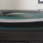
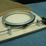
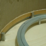
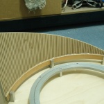
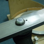
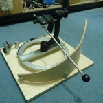
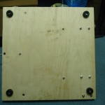
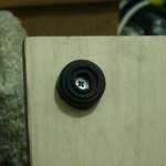
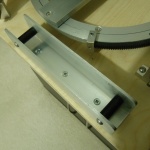
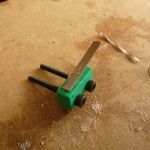
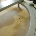
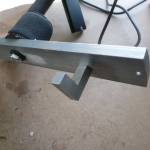
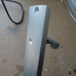
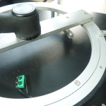
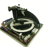
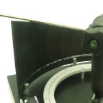
FINISHING ASSEMBLY With the base and mountings completed, I began looking at the drive mechanism and laid out the components to get an idea of spacing and alignment- this was a critical part of the build as any errors would result in chewed gears or a bound up drive train. Luckily, years of R/C experience means that I can eye ball things pretty well and the shaft holders and worm gear mesh just about perfectly, along with the gearbox output shaft and reduction pinions. I would have preferred a metal length of 'rack' to glue and screw to the turn-table, but the tough rubbery plastic seems to be okay so far- time will tell. After that, I devised a simple method for rigidly mounting the Gimbal to its aluminium base, via means of a small stop-pin alongside the large 3/8" bolt- this prevents it from loosening up over time as the pin screws into the aluminium base ( cross bar ) and protrudes into a small hole drilled into the bottom of the Gimbal. Next came the other key component of the whole assembly, the ramp which allows the Gimbal to tilt as it pans from one side to the other. This was made length of flexible MDF and a section of wooden hoop, cut to size and hot-glued together. This was then mounted to the plywood base with three U-shaped aluminium brackets that are bolted in place from the underside- I made these out of some scrap aluminium bar, hacksawed and filed, then drilled and tapped for M4 machine screws. The ramp isn't permanently fixed in place, it's just a friction fit so that it can be removed for travel when needed. Finally for this part of the build, I screwed on four rubber feet to give the whole unit a better grip and more professional look; the underside of the base has a lot of protruding bolt heads and lock nuts, if this were to be manufactured I can imagine the whole thing would be machined and anodized aluminium with countersunk hardware everywhere, not something I could do without the aid of a machine shop sadly.
|
|
|
|
|
|
|
|
|
|
|
|
|
|
|
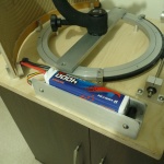
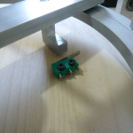
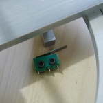
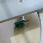
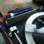
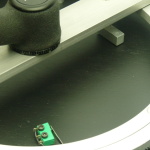
ELECTRONICS With the majority of the building work done, I turn my attention now to the electronics that drive the mechanism. I have a similar controller to the one I used in my Motorised Camera Slider, and plan to have a simple end-stop to prevent over-rotation- only one required this time since the Gimbal is intended to only move in one direction, left to right, as it pans upwards. I have a small selection of micro switches and plenty of wire, I will also most likely use the same Lipo battery as my Slider project, saves buying any more and the voltage is fine, I just need to figure out where to mount it and the controller. Beyond that, the plywood base will get a few coats of matt white paint and some clear coat, then I can move on to testing; the beauty of the Gimbal is that is much more compact than a Slider, and can be transported about far more easily- the Gimbal itself unscrews very easily to make the whole thing no more than a couple inches thick, perfect for slipping in a large bag- compared to lugging around a meter long Slider... Minor tweak after project completion- I added a Diode to the limit switch so that I could still enable reverse- this makes it easier to remove the worm gear and reset the gimbal to the start position.
|
|
|
|
|
|
|
|
|
|
|
|
|
|
|
|
|
|
|
|
|
|
|
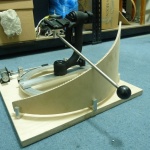
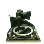
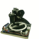
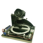
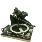
PAINTING AND FINAL PHOTOS For the first time in a long time ( over 4 years ) I decided to make a video, and this time not an R/C related one. Seeing as there is a huge community of 'makers' on Youtube these days, ranging from Woodworkers, Machinists, Welders, Electrical Engineers and everything in between, I thought it would be nice to join in the fun and post my own project video- the Camera Gimbal was essentially completed apart from mounting the electronics and painting it, but since I had to completely dismantle it in order to paint it, it only made sense to film that process and get a project video worth uploading. You'll notice the some of the photos in the Electronics section above show the electronics mounted on an already painted wooden base- that saved a bit of time at the end painting the base and then mounting the parts after it was painted, rather than repeating the process a couple times just for the video. Anyway, I stripped everything off of the wooden base, gave it a good sanding down and then 4 coats of black spray paint, allowed it to dry for half a day then hit it with a few coats of clear spray lacquer to give a durable finish. The next step was simply to reattach the various parts on camera, making sure to get a good close up shot of what I was doing- having to work around a camera and make sure everything is in focus and well lit does indeed turn a short process into a rather lengthy one, especially if you have to re-do something due to a mistake. I mounted the Controller on camera 'for real', and tweaked the wiring for the limit switch and battery lead so they didn't risk fouling the moving parts under the turntable- the little leg that presses the limit switch was in danger of snagging certain wires so I routed them more safely. I put my photography 'table' to good use and generated some very clean ( relatively speaking ) shots of the Camera gimbal in all its glory- I've been having issues getting a decently lit white background, and after some more research it seems I will need to heavily rework my set up, again, but with any luck it will be worth it; I would love to have the space for a proper photography table and half a dozen insanely bright lights and giant backdrops, but I simply don't have the space, never mind.
|
|
|
|
|
|
|
|
|
|
|
|
|||
TESTING AND CONCLUSIONS There isn't really an awful lot to test, but there are some worthwhile notes worth sharing regarding 'numbers'. My initial plan for this project was to have it rotate through a roughly a 90 degree arc over the course of about 6 to 8 hours; the length of track I was able find does indeed give me about 90-100 degrees of rotation, but at full speed it takes 'just' 4.5 hours. This isn't too bad of a result as it happens, since it means I can always dial down the speed with the controller- I might need a larger knob for the potentiometer and mark the travel time based on its position, but I don't see any reason why I won't be able to achieve the desired slower travel time of 6 to 8 hours. UPDATE: After a second test run, I managed to achieve a rotation time of roughly 9 hours with the speed dialled down to as slow as I can realistically set it before there isn't enough power to rotate the mechanism reliably. A nice side effect is also that the noise level dropped significantly too- still noisy enough to be bothersome to anybody nearby, but no where near as egregious as it is at full speed. One thing I don't think I mentioned yet is battery run time- I am using a massively overkill 4 cell lipo with 4000mAh capacity. The cell count is important ( 16.8v fully charged ), but the capacity could easily have been halved and still given me ample run time- as it is, after two test runs lasting over half a day in total, I have barely seen any voltage drop, only a couple millivolts on each cell, indicating the rig would run for days and days before needing a recharge. This makes sense given that the current draw of the motor was listed at 0.1amp, which is next to nothing- it'd take 40 hours to completely drain the battery pack in theory, though I have a feeling it would take even longer based on what I've seen so far. Battery monitoring is by a simple plug in lipo checker that plugs into the balance connector to read each cells voltage- this can be done at any time, even when the rig is in operation, which is handy. One unfortunate finding of this project is the noise level of the device- at full speed the the gearbox and motor unit emit a rather loud hum, so much so that there is no realistic way I could ever use this in proximity to other people, say at a camp site or other out door event where keeping noise levels down is important. At low speed it is less of an issue though still loud enough to be off-putting, there isn't really too much I can do about this as enclosing the motor and gear box is impractical, and any quieter motor options such as stepper motors are cost prohibitive, and still require gearing down which is what introduces most of the noise ( the motor itself is very quiet, the massive amount of gear reduction inside the sealed gearbox creates lots of metal on metal noise ). Elsewhere, the ramp gave me a few head aches as it is not optimally shaped to give a true linear upwards tilt to the camera. Due to the distance between the ramp and the turn table not being constant ( it decreases then increases- I couldn't make it any tighter to match the curve exactly ) there is something of a logarithmic curve, where by the camera starts level, quickly begins to tilt upwards as it rotates, but then trails off and the latter third or so of the rotation results in much less upwards tilt- all this in spite of the ramp itself being completely linear. I don't consider it a real issue in practical terms since if anything, it gives a more gradual end to any timelapse where the upwards motion trails off naturally, rather than continuing at a set angle or rate and the video ending abruptly, as it were. Speaking of which, the final amount of tilt the camera can achieve is 31.6 degrees from horizontal ( assuming the base is set on a level surface ). I would have liked 45 degrees but 30 is pretty good- getting a higher angle would require a tighter, more curved ramp that hugs the turn table. Alternatively, a smaller turntable and accompanying ramp would be needed, but this would also result in a much wider rotation arc, somewhere closer to 180 degrees instead of 90- this could be very useful in certain situations, as could 360 degrees of rotation, but for my needs ( time lapses of the horizon and sky at night ) 90 horizontally and 30 vertically is fine. Ultimately, this was a fairly drawn out project with plenty of challenges along the way but none I couldn't over come or adapt to solve- I had fun coming up with the design, I had fun building it and seeing my crude sketches turned into reality. I expect I will get a fair bit of use out of this piece of kit as it is very simple to use and can give some great results as I'm sure you will see once the project video is completed in the near future- there are plenty of amazing time lapse videos on Youtube and Vimeo, and although I don't quite have the same amazing vistas to photograph where I live, there are still plenty of interesting places to visit and get some footage. Weather permitting, lol. PROJECT VIDEO NOW LIVE ON YOUTUBE, CLICK THE IMAGE ABOVE TO GO CHECK IT OUT! | ||||||||||||||